At the end of 2001/beginning 2002 I spent a lot of time trying to refine the basic design for this preamp which was a result of a journey described here. The list follows the development path of the design I ended up at. Not every design is here but a few to illustrate the direction. I also use this as a place to keep a record of where I’ve been.
Previous designs from 2000 – Present
- Mk3
- Mk4 – never built
- Mk5
- Mk6
- Mk7
- Mk8
- Mk9 Audio
- Mk10 Audio – superceded June 2004
- Mk11 Audio & Mk12 Audio – unrealised ideas for now
- Mk13 Audio – Used temporarily with 813 PP amp – superceded June 2004
- Mk14 Audio – superceded May 2005
- Mk15 Audio – superceded August 2005
- Mk16 Audio – superceded March 2007
- Mk17 Audio – superceded April 2007
- Mk18 Audio, Mk18-1 Audio, Mk18-2 Audio, Mk18-3 Audio – superceded July 2007
- Mk19 Audio – superceded August 2007
- Mk20 Audio – Revised HT feed
- Mk21 Audio – superceded February 2010
- Mk22 Audio – superceded April 2010
- Mk23 Audio and PSU Mk9 – superceded May 2020
- Mk24 Audio and PSU Mk9 – superceded November 2023
- Mk25 Audio superceded July 2024
Design Aim
The aim was to build a MC sensitive preamp that was quiet, used only tubes and had a certain something that made you want to listen. This thing is quiet and if built properly, hum free. I have to put my head very near the speaker to hear a slight trace of hum or hiss at loud listening levels.
The main design aim other than to make it sound good was to give the circuit a solid reference. Single ended circuits “pass on” virtually every bit of power supply noise. This noise may not be audible in its own right but it will modulate the signal passing through the gain stage. Part of providing a solid reference is getting and maintaining an unambiguous and relatively low impedance audio ground. The audio ground is a single foil conductor about 20mm long. All the audio components are connected to it using their leads only – no extra wiring is used. The circuit is shown almost exactly as it is wired.
Another design aim was to trust the components to do their job. “A sound” was not the aim but it was designed to allow as much as possible to be heard detail wise but also to maximise the connection to the musician(s) and allow the musical message through. This is very hard to explain and I was surprised how delicate this balance was. The simpler it got, the better it became up to a point. The more iron/coils I threw at it, the better in these terms it became especially rhythmically.
Any additions to “help” the circuit such as active/CCS loads and regulators etc got in the way. As the PSU got better, the less these things were needed. If the PSU is average, then these circuit “tricks” can be used to advantage as they isolate the audio circuit from bad power supply artifacts.
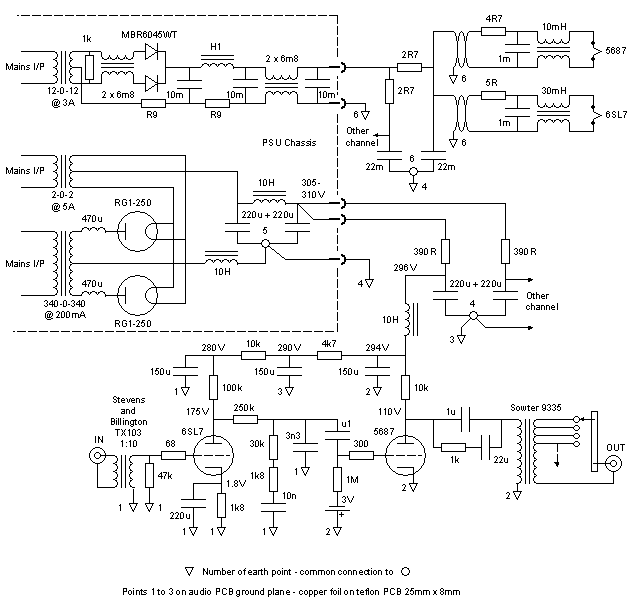
PSU Circuit Description
After using dual mono supplies for years, it occured to me that it is impossible to provide a common clean ground reference using this approach hence the main outboard supply is mono in design. The sound seems more coherent this way. The transformer is 4x overated for the duty – whether this is needed for choke input is debateable. Rectification is by MV diode rectifiers – they were not compared to other types but are effortless in sound and look brilliant. The small inductors in their anodes suppress their tendency to ring a bit on start of conduction. The supply is choke input which provides a big easy sound – preferred to capacitor input. All transformers have earthed electrostatic screens.
Modelling using the superb Duncan’s Amp PSU designer produced the design results. The DC voltage as modelled was 298V; 301V in reality using the 83 rectifier and design values for the chokes. Note the transformer is 340-0-340 @ 200mA so measured about 370V with the load of the preamp circuit. Ripple at the PSU output modelled at 0.5mV. After the RCLC stage, ripple is approx 20nV and will be much less for the first stage. I can’t see any regulator achieving these figures and so contributes to the quietness and lack of program induced noise that indicates a poor power supply.
The heater supply is similar in topology to the HT and contains the only solid state device, a schottky dual diode. The 0.1H 3A chokes decimate ripple and therefore even in an MC sensitive preamp, no regulator is required for low noise/hum. The common mode choke helps to attenuate hash and rubbish that has come in on the mains or transients caused by the diodes switching. The secondary also benefits from a resistor which I guess damps oscillations caused by diode switching. A similar arrangement on the HT produced no discernable benefit.
Audio Circuit Description
A key component in this design is the TX103 Stevens and Billington MC step up transformer. A superb device; the closest thing to a wire with gain I’ve heard and that is exactly what I replaced when I tried it – a piece of wire. I’d concede it is the superiour matching and energy transfer that this allows to be crucial. All previous transformers I’ve heard have obscured something or other so straight into a high gain stage has been the past norm. Haven’t heard the more expensive Jensens or other exotics.
The first tube sets the scene; it being the first amplifying device in the system. For ages it was a 6SL7, then a triode wired D3a and now D3a as pentode is used. The 6SL7 just didn’t have enough grunt to drive the EQ properly and so sounded much like the EQ curve itself. The D3a has a more powerful even sound. Having tried self bias for most of its development, fixed bias is a worthwhile improvement and does away with cathode bypass caps which would be huge with this type of valve. The cascaded plate decoupling essential for the 6SL7 has not been tried with the D3a.
The RIAA is nothing special – modelled in LTSPICE, parts bought and bunged in. The model claims approximately +/- 0.1dB, 20Hz – 20kHz and I have no test equipment accurate enough to verify this. The raw calculations can get close but theory requires the load R to be 50 times that of the series R. This clearly is not possible in this type of circuit so the series R has to be altered to suit. Luckily, the standard value capacitors fit fairly well with series resistor combinations used to make the correct values. The extra 820R in series with the 3n3 restores the time constant used in the recording process to limit HF boost – not part of the RIAA specification highlighted by Allen Wright. His “Cookbook” is good for ideas too although I wouldn’t agree on all of them.
The output stage is a NOS JAN Philips 5687 driving the other key component in this design, the Sowter 9335 transformer volume control (TVC). This allows galvanic isolation of the preamp and full energy transfer of the signal to the power amps. No resistive control can achieve this as they all waste power. The 5687 is fixed bias as it seems to prefer this sonically.
However the 1u coupling capacitor is not large enough and in conjunction with the 80H primary inductance, creates a resonant circuit around 17Hz. To get this below where record warps and the like are an issue requires about 20u but a cap alone that size sounds bad. “Lossy parafeed” gets round this problem and also sounds very good – way better than the 22u or 1u alone.
Since May 2005, the lossy parafeed idea has been replaced by a transformer in a parafeed arrangement. The TVC has been moved outside of the phono amplifier to enable other inputs to be used in a line stage.
There are no bypass or paralleled capacitors in the design. If a part “needs help”, then the parts selection must be wrong. Paralleling of devices smears the small details and ruins timing in every case I tried it. Get one thing to do one thing well was a design aim.
Audio Power Supply Circuit Description
Channel isolation is key to good soundstaging and dynamic interplay but a common reference is also required. More than 2 chokes in series can be very difficult to get stable hence the RC decoupling used to provide channel seperation. A further LC stage brings out the dynamic and timing capabilites more.
For the heaters, a common mode choke helps to attenuate hash and rubbish that has come in on the mains, picked up on the umbilical or caused by the diodes switching and maybe bypassed the big chokes. Each heater is RC decoupled; the final element being a common mode choke providing isolation. Each heater has it’s own voltage adjustment – well worth the extra cost as it’s very hard to get them all balanced otherwise. This supply contributes to the freedom in dynamics without the hashy and grey sound that DC supplies and regulators often cause. Elevating the supply to about 50V also improves sonics. A 9V battery was also used for a while to elevate the heaters and is worth trying.
Components
The component selection determines the flavour. The selection I made is not based on “a sound” but what sounds right to me and allows the most information, music and detail, through. I like a big, lively, open and relaxed presentation and dislike hyped over-etched detail and sogginess. I guess these characteristics are all relative though. Virtually any component not made of pure materials sounds grainy, glary or both. So metallised capacitors are avoided (even in the PSU) as are plated wires where possible. Other than that, I have no real prejudice against component types.
All coupling capacitors have been film/foil polypropylene North Creek Crescendos. Capacitor values were chosen for a very low LF rolloff. LF extension allows the size of the recording space to come through but it can cause problems further down the chain if either the record is warped or the cartridge is not damped when riding the odd ripple. The 6SL7 cathode bypass is a Black Gate Nx type. The RIAA caps are 500V 1% silver mica. The “lossy parafeed” 22u is a Black Gate VK type. Have yet to try a better model in this position.
All PSU decoupling capacitors are Black Gate VK types and are again highly recommended and preferred to any polypropylene type I’ve tried as all are metallised in this size. The PSU 220+220u capacitors are Black Gate WKz types.
The LT PSU electrolytics are BHC Aerovox ALP22 and were preferred to computer grade types I tried.
The resistors are ordinary metal film and Mills WW for high power (5687 anode load). The cartridge load is a S102 Vishay. The resistors do make a small difference. At one point the whole thing was using Rhopoint WW resistors but this sucked the life out of it and made it impossible to discern differences in the TT – a very expensive mistake.
The 5687 bias battery is Lithium Maganese with wire leads while the D3a bias is an alkaline for now. The grid stoppers are cracked carbon and preferred to RF beads or other resistor types.
Good quality iron from Majestic Transformers has helped too. The 2nd and 3rd HT chokes and 2nd LT choke use a design by Mladen Krklec; more in keeping with a plate choke than a regular PSU choke.
All PSU wiring is twisted pairs of Kimber TCSS while the audio uses Kimber SF24+.
Construction
This preamp has been rebuilt about 10 times in all. This would not have been possible if there had been circuit boards or chassis work. 9 of those were on unetched fibreglass and point-to-point construction. This current build is the easiest and best sounding to date.
No mounting board is used so it’s like a “free standing bird’s nest” style construction – not very rugged but is when the tube sockets are fixed to posts. The design allows easy replacement of virtually any part without case/board rework.
Many times, prototypes sound way better than when they are put in a box especially one containing aluminium or ferrous metals so this one stays on its board and the top and sides of copper foil covered ply built around it. Construction has now moved to hard wired on a blank PCB using the copper as a ground plane and PTFE turrents for some components.


Earlier version inside, Audio layout, close up and PSU “plank-o-wood”
Update – March 3rd 2003


Sides finally, Top view, Close up and 1 channel close up
Update – April 27th 2003
Corespondance with someone who built the circuit led me to rethink the RIAA EQ as it seemed to be bass heavy. This was corrected and at the same time, the first stage was changed to battery bias which improved things a bit. Battery elevation of the heaters was an improvement on the usual RC divider arrangement.
Update – June 5th 2004
Changed the input valve to triode wired D3a and remodelled the EQ more accurately. This is a big step forward so text revised on this page to suit.
Update – April 9th 2005
Getting something into a case is not something I do well. I like to have some case though that can accomodate modifications so “breadboard in a box” construction is what I use. These are storage boxes from a DIY store. They even have cutout handles to help carry them. The whole circuit fully wired can be removed from the box without desoldering anything as the base is the breadboard and all sockets are mounted from the inside.


Phono audio outside, inside, PSU outside , inside
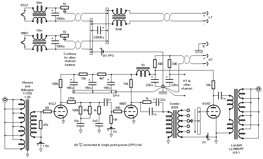
Update – May 5th 2005
The lossy parafeed idea was never a favourite of mine but was used to get round a problem – that is capacitor coupling to a TVC or transformer having lowish inductance. Having some Lundahl 1544a transformers lying round, I tried them on the output getting rid of the 20uF cap in the process. This proved to be a nice improvement and technically a better solution. In terms of magnitude, is is hard to describe but I’d rate it as one of the biggest in the development of the circuit. I tried some Sowter 3575 and while good, they weren’t in the same league as the Lundahl amorphous core types but neither did they cost as much.
Update – August 7th 2005
The bird’s nest style construction was never totally successful re hum so rebuilt it on the PCB ground plane style again. Not only does it look better but it also sounds better this way. Hum is usually an indicator that the construction is not optimised. Even though the wiring remained unchanged, the construction method and layout are important to get the best result. Sometimes we have to be reminded of this.


PCB bottom, top sides and inside case
Update – August 18th 2005
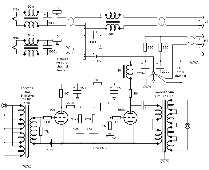
I wanted to move the topology along the lines where I could try different types of EQ without altering the rest of the circuit. That would involve transformer coupling the first to second stage. I had a Sowter 3575 lying about so implemented changed the coupling method to parafeed. This has produced quite a large improvement that on first glance doesn’t look possible however on closer analysis of the AC loops involved, it can be seen that the signal sees a less complicated path. In addition, the EQ becomes simpler as there isn’t the grid resistor on the second stage which previously increased the insertion loss by 2dB. This is only preliminary and needs a little fine tuning but so far, a big step forward.
Modelling further has shown better values for the EQ. The Sowter 3575 is not suitable in this position in a parafeed configuration. The rise due to series resonance with the capacitor exacerbates records warps and accentuates the bass in a boomy way. However the Lundahl 1676 does not do this; it having an amorphous core. Some further listening will determine the best positions for the 1544a and 1676.
The circuit for the above was the Mk16 Audio using the 1544a first and the 1676 on the output until …
Update – March 3rd 2007
I used the previous circuit, the Mk16, for 18 months and was very happy however there was always the lingering thought that a lower Z EQ might be better. A friend got there before me and he thought it was so recently I got the parts and tried it. It’s hard to describe fully what this does but the music has more of everything; dynamics, sparkle, detail, involvement. There seems to be less noise and gunge. The capacitor types were the same; silver mica. I still have to try to see which position best suits the transformers. Mk17 Audio
Update – April 10th 2007
A thread on Audiogon got me thinking about the use of the d3A in triode mode. High gm valves tend to have high grid to anode capacitance. On high mu valves, this is multiplied by the circuit gain which with a mu of 80 is high. This is then magnified by the square of the turns ratio of the input transformer. The capacitance the cartridge sees can therefore be huge and this became a concern. I had been thinking the top end was not all it could be either. Some basic calcs led me to believe the resonant frequency of the cartridge would be about 20kHz; not good! So a low input capacitance device would be more ideal so I converted the input valve to pentode configuration and was very pleased with the results. This is a first try so nothing has been optimised yet. Mk18 Audio
Update – July 22nd 2007
I wanted to seperate the 2 stages more from one another. With transformer coupling between the stages, the need to have the same ground looked like a compromise. So the supply was re-arranged using the same components into this Mk18-1 Audio. This also improved the sound a little … well more than I thought it would.
I could now try choke load on the output stage. This I liked a lot! Mk18-2 Audio
I don’t know why I didn’t spot this earlier. By arranging the output stage a bit, the battery could be eliminated. Soundwise I preferred this new arrangement Mk18-3 Audio too which was a bonus.
I then split the grounds resulting in the Mk19 Audio This improved the sound further.
Apart from the choke loading, the rest of the mods came for free and while not earth shattering advances, they are very worthwhile.
Update – August 2007
Like the output stage, rearranging the input stage enabled the battery to be eliminated. Again, I preferred the sound of this. Mk20 Audio
Update – February 2010
After moving house, the new environment had thrown up some low frequency problems. Simulating the circuit more accurately in LTSPICE revealed an LF hump caused by the parafeed transformer in conjunction with the EQ. This was very audible and unworkable with the Sowter but I thought technically fine with the Lundahl. In the new setting this was not so and what was better in the last house seemed to be causing problems. So I revised the circuit to cap coupled and heard a vast improvement. It would seem the LF was overloading the system and squashing dynamics. Since putting the transformer in, a lot of the circuit changed around it and it is now not applicable to the pentode front end. If I wanted to go LCR in the future, there are ways to do it without the need for a coupling transformer which was the purpose of having it in the first place. So now the circuit is Mk22 Audio
Update – April 2010
Due to the last update, I wanted to try getting rid of the parafeed output and keep transformer output but I didn’t have a suitably gapped single ended transformer to hand but I did have a Lundahl LL1660 gapped for PP use. I had a spare half of a 5687 sitting there doing nothing. I converted the output stage to a diff amp which also enabled me to direct couple. One day I’d like to try it single ended (That idea took about 13 years, 2023, to try out) but for now, I’m very happy with this Mk23 Audio.
I also wanted to try a different “breadboard in a box” idea. The one I’d been using up until now was 7 years old! Getting at the underside of the boards on it was proving to be hard work over the years. If I could elevate the board to mid case then access would be better. If I could get the breadboard out of the case without having to unscrew anything, then I might be more inclined to update it. The pictures below show how it worked out.


Upside down, Right way up, Slid into case and lid on